Mechanical Design
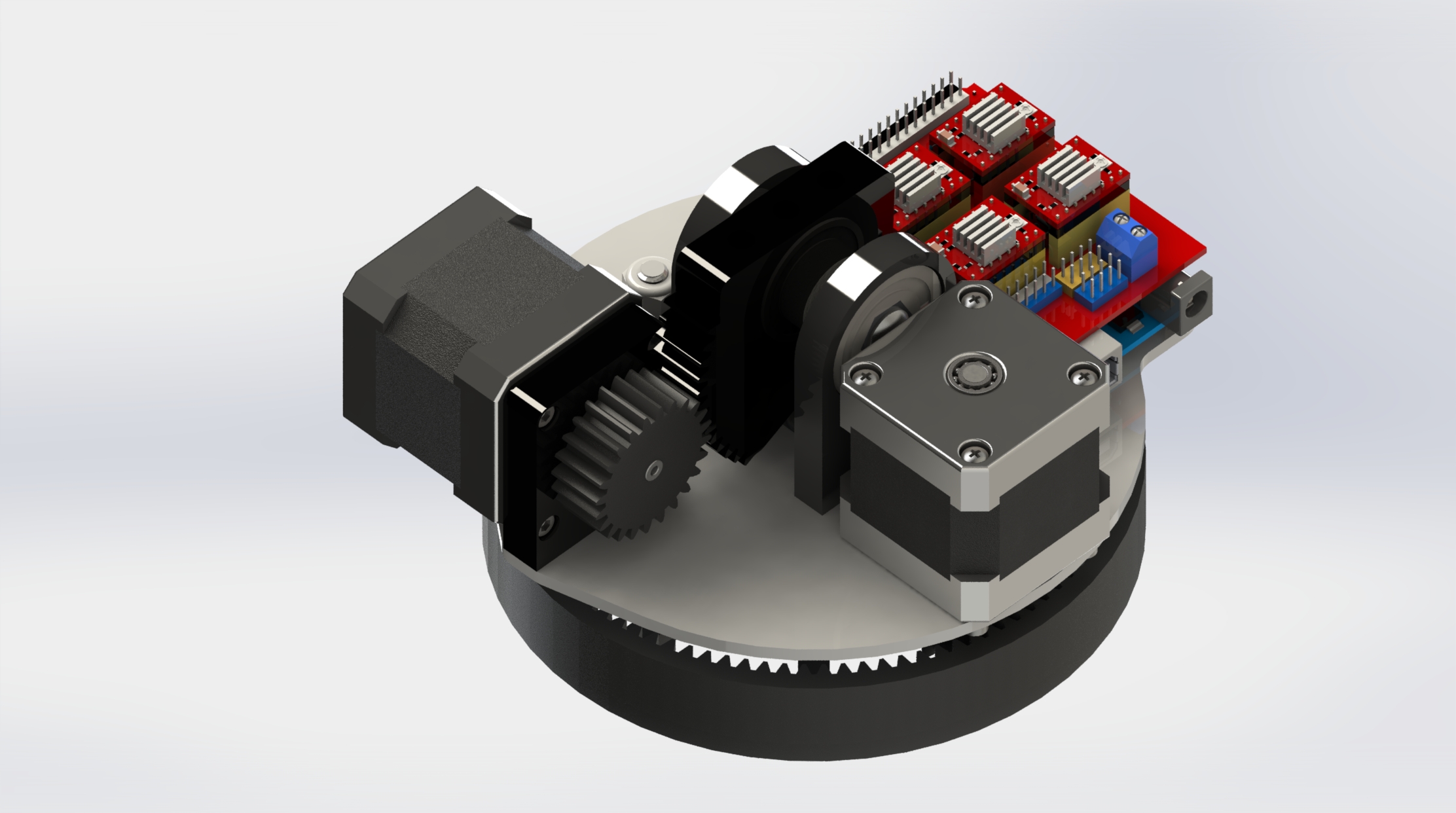
The turret uses a nested gimbal architecture with two orthogonal rotational axes: a vertical azimuth (yaw) axis at the base and a horizontal elevation (pitch) axis at the turret head. The base assembly houses the yaw stepper motor and a thrust bearing to support the rotating upper structure against axial gravity loads, while the turret head pivots on the pitch axis through a pair of flanged sleeve bearings pressed into the side frames.
All structural components were designed for FDM printing in PLA+ with 0.2 mm layer height and 40% gyroid infill, balancing print time against the bending stiffness needed to resist stepper motor reaction torques without visible deflection. Wall thicknesses were set to a minimum of 2.4 mm (6 perimeters) at motor mounting interfaces to ensure adequate thread engagement for M3 fasteners into the printed bosses.
Stepper Motor Control
Each axis is driven by a NEMA 17 bipolar stepper motor (1.8° native step angle, 0.4 N·m holding torque) through an A4988 chopper driver configured for 1/16 microstepping. This yields an effective angular resolution of 0.1125° per microstep — sufficient for smooth, jitter-free motion at the slew rates required for tracking applications.
The Arduino Uno generates step and direction pulses for both drivers using hardware timer interrupts, enabling simultaneous coordinated motion on both axes without blocking the main control loop. Trapezoidal velocity profiles with configurable acceleration ramps prevent step loss during rapid slew commands by keeping instantaneous step rates within the motors' pull-out torque curve.
Modular Sensor Integration
The turret head incorporates a standardized mounting interface — a 40 mm × 40 mm bolt pattern with M3 threaded inserts — designed to accept interchangeable payload modules. Evaluated payloads include a PIR motion sensor module for autonomous area scanning, an ultrasonic rangefinder for distance-gated detection, and a camera module for visual tracking applications.
For the camera-based tracking mode, an external host computer running an OpenCV pipeline processes the video stream, extracts target bearing and elevation offsets, and transmits angular correction commands to the Arduino over serial UART at 115200 baud. The turret's control loop executes these correction commands as incremental step moves, closing the tracking loop at approximately 15 Hz update rate — sufficient for tracking slow-moving objects within the sensor's field of view.
Design for Assembly
The turret was designed with snap-fit joints and captive nut pockets to minimize hardware count and allow tool-free disassembly of the head from the base. All printed parts self-locate through mating features (boss-and-pocket) that constrain assembly to a single correct orientation, eliminating the possibility of mis-assembly. The total assembly consists of 14 printed components, 2 motors, 2 bearings, and 18 fasteners, with a complete build time under 20 minutes from printed parts.