System Architecture
The differential swerve module employs a coaxial dual-motor input driving a bevel gear differential to independently control wheel rotation speed and steering angle from a single mechanical package. Both motors are mounted concentrically along the module's vertical axis, eliminating the offset mass and packaging constraints associated with conventional swerve modules that use separate drive and azimuth actuators.
When both motors rotate in the same direction at equal speed, their torques sum through the differential and the wheel drives forward. When the motors rotate in opposite directions, the differential redirects the torque to rotate the entire module about its vertical steering axis. Any combination of same-direction and opposing-direction input produces simultaneous drive and steer — giving the control system continuous authority over both degrees of freedom through motor speed commands alone.
Differential Gear Train
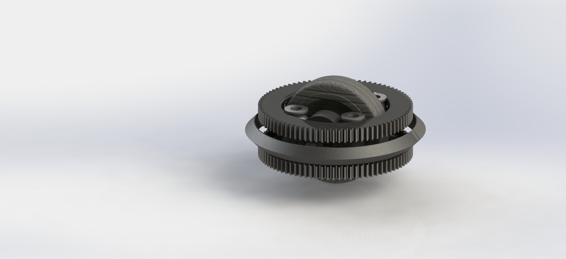
The core of the module is a bevel gear differential consisting of two input bevel gears meshing with a set of spider gears mounted on a carrier. The spider gears act as the torque-splitting mechanism: equal and opposite inputs produce pure carrier rotation (steering), while equal co-directional inputs produce pure axle rotation (drive). The bevel gear geometry was selected for its compact axial footprint and the ability to transmit torque through a 90° axis change without additional reduction stages.
Gear tooth profiles were modeled in SOLIDWORKS with involute curves sized to handle peak motor stall torque with a minimum safety factor of 1.8 on bending stress per Lewis beam strength analysis. The spider gear pin was designed as a press-fit steel dowel running in self-lubricating Delrin bushings to minimize friction losses through the differential.
Rotational Base & Bearing System
The wheel fork assembly rides on a large-diameter thin-section bearing that supports both radial and axial loads generated during combined drive-and-steer maneuvers. The bearing's inner race is fixed to the chassis plate while the outer race clamps to the rotating module housing, allowing continuous 360° azimuth rotation with no hard stops or cable wrap limitations.
All structural housings and the fork assembly were prototyped in PLA and PETG via FDM 3D printing, allowing rapid design iterations on wall thickness, bearing pocket tolerances, and gear mesh alignment. Final-revision bevel gears were printed in Nylon PA12 on an SLA machine to achieve the surface finish and dimensional accuracy required for smooth gear mesh engagement.
Holonomic Drive Kinematics
A four-module swerve chassis using these differential modules achieves full holonomic motion — the robot can translate in any direction while simultaneously rotating, with no non-holonomic constraints. The inverse kinematics solver decomposes a desired chassis velocity vector and angular rate into per-module wheel speed and angle targets. Because the differential decouples these into simple motor speed commands, the control loop reduces to independent PID velocity control on each motor with no additional azimuth position controller required.
This architecture eliminates the azimuth encoder, slip ring, and dedicated steering motor found in conventional swerve modules, reducing part count and mechanical complexity while maintaining the same kinematic capability.